Contributors:
Balakumar Sundaralingam, Rohith Prasad.
Introduction
The use of tele-operated robots in search and rescue, environment monitoring and interstellar exploration has increased in the past years. Tele-operation of robots is a complex task. The operator not only has to focus on the task but also perform collision avoidance so that the robot does not collide with obstacles in the environment. The addition of an automatic collision avoidance system to the robot will ease the operator and allow the operator to focus more on the task. This idea is not entirely new, as it has been in use in medical telerobotics as virtual fixtures.
Collision avoidance for mobile robots can be applied to unmanned ground
or air vehicles for disaster response, precision farming, space exploration, environmental control and
monitoring. Collision avoidance methods are in two broad
categories- path planning methods and methods for local collision
avoidance. Path planning methods are used to find a path to the goal
given a map. Path planning methods are not of much use in the absence of
the knowledge of the environment. Local collision avoidance methods
determine a collision free path between two close points in the
environment. Most common approaches being vector field
histogram, artificial potential field
,curvature velocity methods and
dynamic windows. Artificial potential fields is taken as the method to
perform automatic collision avoidance for its ease of implementation.
Problem Definition
Given an holonomic ground robot controlled by a human operator, the robot has to avoid obstacles in its path. The following assumptions are made pertaining to the problem:
The environment is made of simple obstacles.
There is at least one collision free path.
The robot at any instant only knows about its surroundings and does not know the global map.
Approach
The approach has two parts. First the artificial potential fields approach is discussed followed by the addition of user input to the system to get the robot to move along the user desired direction.
Artificial Potential Field
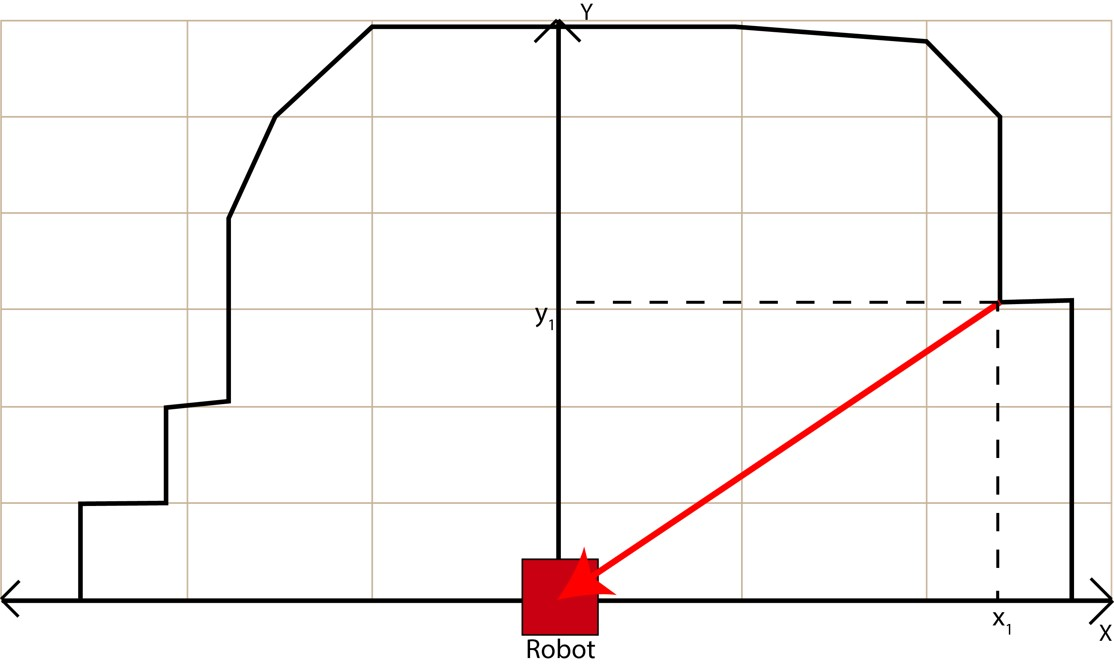
The artificial potential fields method is taken and modified to perform local collision avoidance. The first modification done is to remove the goal attraction property. The readings from the local sensor cause forces to act on the robot. The forces from the sensor are inverted and scaled so that nearer objects cause more force.
Forces from Obstacles: $$force_{x_{i}}=\frac{1}{x_{i}}$$ $$force_{y{i}}=\frac{1}{y_{i}}$$ $$Force_{x}=\frac{\sum\limits_{i=0}^{n}force_{x_{i}}}{n}$$ $$Force_{y}=\frac{\sum\limits_{i=0}^{n}force_{y_{i}}}{n}$$ where $x_{i}$ and $y_{i}$ are the forces along x and y axes from the $i^{th}$ obstacle point. n is the total number of obstacles(in the case of a LIDAR, it is the number of non-zero points). $Force_{x}$ and $Force_{y}$ are the resultant force vector components along x and y axes.
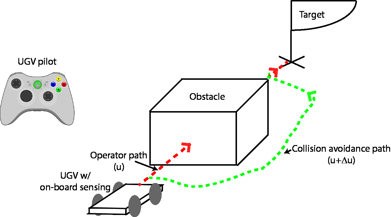
User input
The user input has to be used in a way such that the operator feels at home, so being an holonomic robot, the additional degree of freedom(yaw) is not considered as an input to the approach. The directions are taken as the input instead. When no direction is given as user input, the approach takes the forward direction as the heading and the user can change the yaw to traverse the environment.
$$\theta=tan^{-1}(\frac{Force_{y}+user_{y}}{Force_{x}+user_{x}})$$
$$Velocity=\sqrt{(Force_{x}+user_{x})^{2}+(Force_{y}+user_{y})^{2}}$$ where $user_{x}$ and $user_{y}$ are the x and y components of the tele-operator commands.
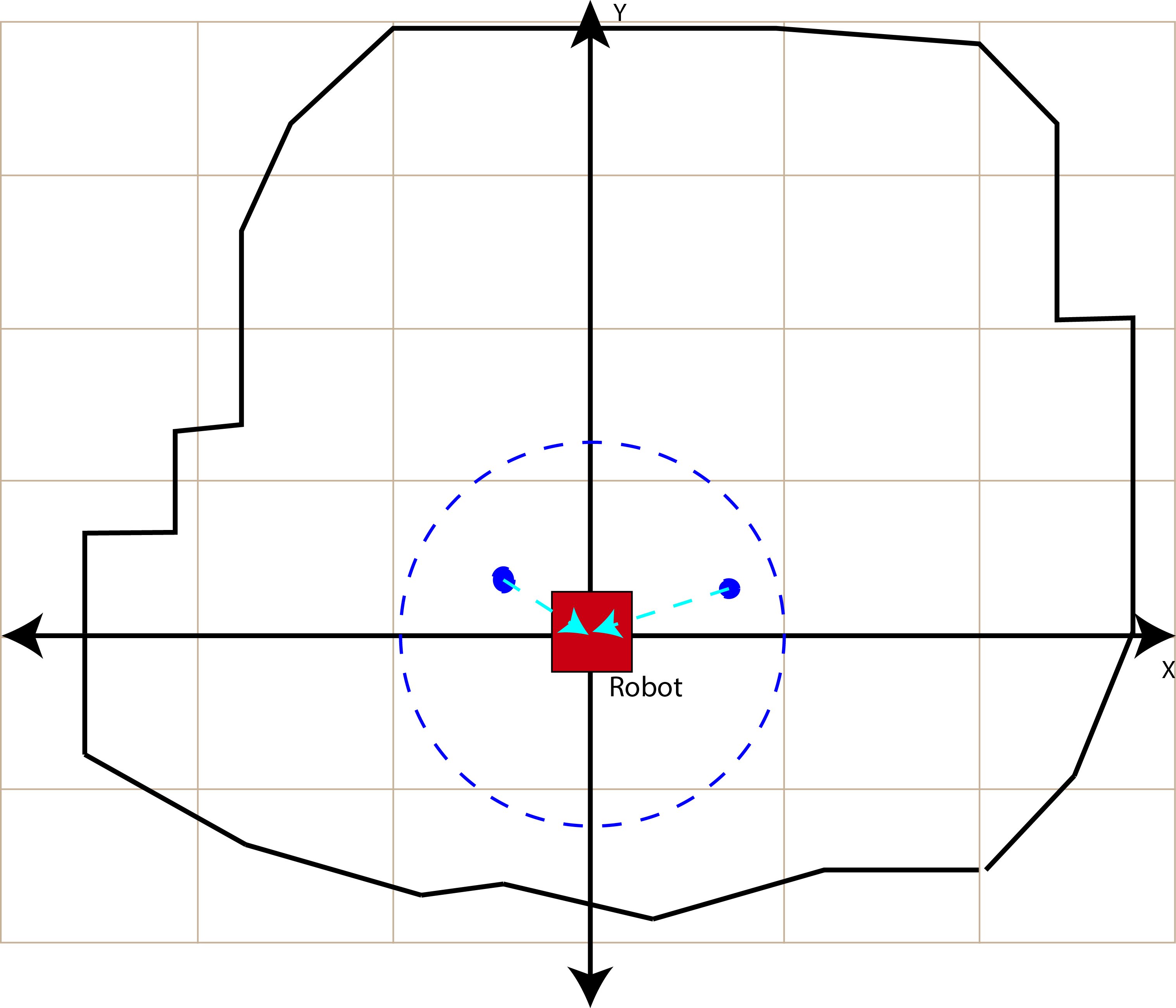
Implementation Issues and Challenges
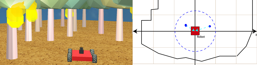
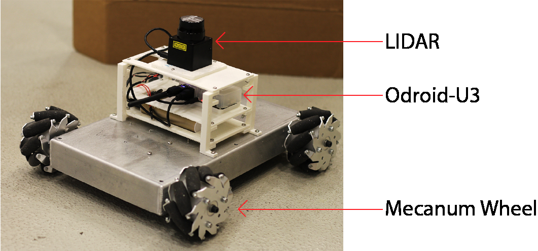
The LIDAR sensor used in our tests was a 360RPLIDAR which has a range of
6 metres. When the entire 6 metres is used, the robot has a lot of
oscillations and was very unresponsive due to very high forces. To make
it more reactive, the effective radius of the potential field is reduced
to 0.6 m. This makes the robot be
more reactive and has very few oscillations.
Results and Discussion
System Setup
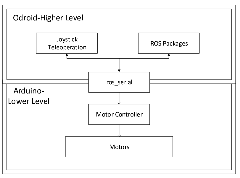
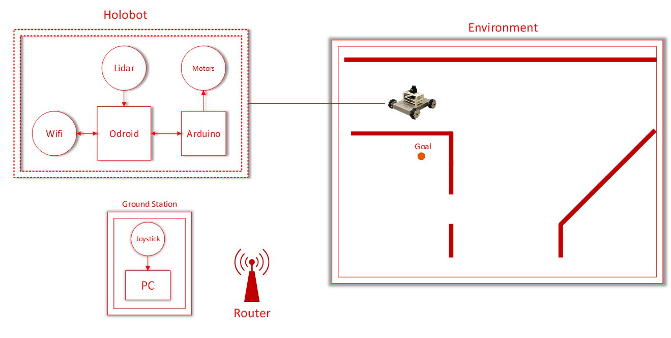
The system used for testing the approach is a linux computer with AMD FX8320 CPU and 8 GB of RAM. The robot has an on-board single board computer which is called ODROID-U3 which sends the LIDAR data back to the main computer . ROS is used as the framework for implementation of the approach. For simulations, VREP is used with different environments.
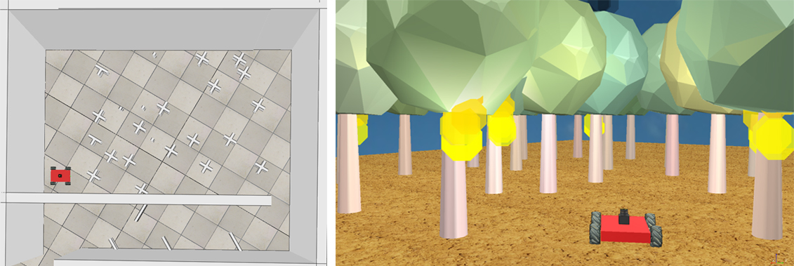
Test environments
The tests were performed in simulation and as well as in real world. For
simulations, four environments were designed. The real world tests were performed in hallways
and an office lobby. The submitted video has the collision avoidance
system working and preventing collisions.
Analysis of Results
The initial tests with no effective radius in place was not very promising and had a lot of oscillations. After creating an effective radius, it was seen that the robot was more responsive and avoided collisions in a better way. However, the robot had oscillations in tight spaces which is an inherent drawback in the artificial potential field method of collision avoidance. The reduction in effective radius allowed the robot to have a smooth path along hallways and stay away from obstacles. The use of yaw to steer the robot was easier than compared to giving user input in different directions. So the robot had a constant forward heading and the robot was navigated in the environment using the yaw. If the robot went close to an obstacle, the potential field algorithm kicked in and moved the robot away.
Conclusion and Future Work
The results from the approach looks promising, especially the addition of user input in a way so that the tele-operator is not put into burden. There are drawbacks in the approach which are due to the artificial potential field method. The main goal of implementing a potential field system in a tele-operated robot proved successful. For future work, the magnitude of the user input will be included in the collision avoidance system. Also the use of a more robust collision avoidance approach such as vector polar histogram might be feasible.